2016年3月31日 星期四

@ TA-954 TT Military DNVT (US 美軍軍用電話-數位非安全語音終端機)

7 years ago, had got a TA-954-TT of Taiwan-Ruten webside with cost of $ 6000 NTDs but just pigeonholed in my storeroom,.Turned out that this phone and found this one was made by 1984-YR for 32 years soldier field communication partner. 

Nowadays I consider to chop the plug off the cord, and trying to tear down for new converting.

The digital non-secure voice terminal (DNVT) TA-954/TT is a four-wire terminal
contained in a ruggedized case, which transmits and receives conditioned diphase-modulated
digitized voice and loop signaling information at 16 or 32 kb/s. The DNVT has a 16-key push
button keyboard, receiver and ring volume controls, an incoming call/off-hook indicator light,
and writing pad. It contains built-in protection from nuclear energy electromagnetic pulses
and lightning. Handset H-350/U is issued with the DNVT. The microphone element is
activated when the handset is removed from the cradle (hot mike). The push-to-net radio
interface switch is only pressed to key the C-6709. The DNVT provides a digital
communications interface with Tri-Service Tactical Communications (TRI-TAC) and Mobile
Subscriber Equipment (MSE) circuit switches.

Technical Characteristics :
Channel Interface-Field Wire  .................... 4-wire field cable
Transmission Range................................... 4 km (2.4 mi) max
Input Power-Power Drain:
On Hook .................................................... 300 mW, max
Off Hook..................................................... 1.5 W, max
Power Requirement .................................. +24 to +56 V DC
Line Impedance ........................................ 125 ohm
Tone Pad.................................................... Characters 0-9, FO-F-I-P-R-O-C
Current Drain:
On Hook.................................................... 12.5 Ma, +24 V DC, 5.0 Ma, +56 V DC
Off Hook ................................................... 62 Ma, +24 V DC, 25 Ma, +56 V DC
Weight....................................................... 2.7 kg (5.8 lb)


TA-954/TT ID card


Left side are interface connectors and 16/32K B/S Rate switch,and 4 XMT/RCV binding posts.

Bottom side


Handset of H-350/U with 6 I-type screws, not easy to open the handset case.With Amphenol
6 Way Cable Mount Connector


All 10 screws are un-hooked and the sockets are essentially impossible to purchase in separately. But would just be easier to tear-down a compatible field telephone. So upon the TA-954/TT here by is to recover that neat-looking keypad.

None of the screws are hidden under stickers, and they are all thread into brass insertions. Pretty good concern.


Modification on military equipment is quite interesting.
Unlike consumer electronics device, military designers know that MIL products will be used by men
in extremely sandy conditions also would be shot at occasionally.

The electronics components are protected from environmental incursion by an amusingly convoluted seal,

which are lubricated with amazingly tenacious grease. On the left side, all the interface components with the main board and line terminals on right side.
The round shape device is the metal ring speaker.


The interface electronics components are pretty standard but all the military grades. 
the rectangular board on the upper left side might be some sort of hangup sensor,
and the pots on the upper right are volume controller.

Lower middle side is the keypad, which appears to be secured with four (metric) nuts,
then glued down. Lower right side is a visual ring indicator.

What a cool older 80s electronics design with lots of discrete ccomponents.
Everything is coated with a waterproofing and anti-corrosion varnish,

* The enormous 8-bit 8051 microcontroller with 2.048 MHz round Oscillator.

* Texas Instruments' general metal diodes and Motorola metal small-signal transistors are found.

Input Tr and output Tr are set as bigger pair,moreover the ring type inductor is designed picked up.

The main board is connected to other sub-module boards through a 40-pin ribbon connector/cable.


Look over the board, no RF shielding or optoisolators cab be found,
which means that designer didn't concern the EMP harden factors but the case metal material can provide EMC/EMI protection.
Since in operation the TA-954 field telephone would be connected to hundreds of meters using telephone cable.

The socket appears to be molded into the case, but is impossible to liberate without extensive surgery.
So will try my hand at splicing a field telephone cable.


   Main Control PCB Top


   Main PCB Botom


Turns out that !


These look like a bunch of beefy inductors and zener diodes.
They probably kill surges and line noise,
since there's nothing like a faraday cage in evidence,
and there is multiple unshielded penetrations through the casing.
(Such as volume controls, keypad, etc)


   Main MCU and 2.048MHz Oscillator ,especially for transmits and receives conditioned 
   diphase-modulated digitized voice and loop signaling information at 16 or 32 kb/ s. 

   Input and Output Transformers

   Interface Board Top


   Interface Bottom


   Hand Set On-Hook Sense Board


   Incoming LED Indicator TOP

   Incoming LED Bottom


   Outer 4X4 Keypad Module


   Keypad Bottom of 4-Row / 4-Col w/o ground signal flying 


   Keypad Matrix Table and Pinout


   Vintage Magnavox Ringing Speak 

   Ringing Speak Bottom


   XMT & RCV Block/Red binding heavy duty posts

Beating on the handset socket some more revealed that it was actually screwed into the case,
not molded into it. 
My next step is to convert it with "used" home-style telephone boards ,
modify / adapt some man-made PCBs for the keypad / interface / ringing indicator circuits!

2015年1月9日 星期五

@ Change Code::Blocks SDK Editor Theme (Windows-10)

There are a lot of pre-defined color themes in this wiki page: Syntax highlighting custom color themes.
In this blog, I will show how to use these themes in Code::Blocks under Windows-10 platforms

1.First download the colour_themes.conf file by gist.github.com webside
   (Make sure Code-Blocks is not running.)

2.Run "cb_share_config.exe" file. It should be under the folder where you install Code::Blocks.
   And then you can see the "Welcome to Code:Blocks Share Config" Window..
   The load the "colour_themes.conf" file on your left side and the "default.conf" file is on your right.
3.Select the themes that you want to import to Code::Blocks by clicking the check boxes on      the left 
   and then select Transfer>>> and Save as well.

   I will recommend to select all of them.


4.Open Code::Blocks. Go to Settings > Editor > Syntax highlighting.
   All the themes that you have imported will be available under the color theme drop list.


5.After change the theme. You may notice that the insertion bar become hard to see
   if you use a dark background.
   But you can modify the color of the insertion bar under: Settings > Editor… > Margins and caret.   
   Change the color of the caret to some brighter colors.


 ** Also I have installed Code::Blocks Rev 16.01 on my notebook and migrated the SDK to
     chinese version.If you are searching the chinese translation package, you can download
     the dedicated "zh_TW_LC_MESSAGES_codeblocks.mo" file by following link:
     (My MEGA Web)→→ Download

2014年3月29日 星期六

@ Power Supply DIY

Adjustable DIY Power Supply - YR 2014

The 2014 latest had almost perfect - two channels, 1.2 - 30V/3A -
but there was no current limit. That's why I had search for suitable schematic to build.
What I found is this schematic: http://www.electronics-lab.com/projects/power/001/index.html.
It provided adjustable output voltage from 0 to 30V and adjustable max output current from few 
mili-amperes to 3 amperes.
As it turned out there are serious flaws in it, but in the forum where it was thoroughly discussed
and one of the member had proposed an improved schematic, in which all flaws were been addressed.
I used his schematic to build the new power supply.


   In the final version
   there will be a much bigger heatsink and maybe also a fan.

After built it and did some tests I made two changes: 
first, added 24V zener diode and resistor to stabilize supply voltage on IC1. 
This is especially important because when there is higher load and supply voltage drops 
by some volts the reference voltage on pin 6 would be changed significantly.
Second, had removed 10k trimmer resistor RV1.No need to use it anymore.

Here came the final schematic version:


The two trimmers are used for adjusting the max output current and the max output voltage.

Some snaps of the PCB and assembled board:


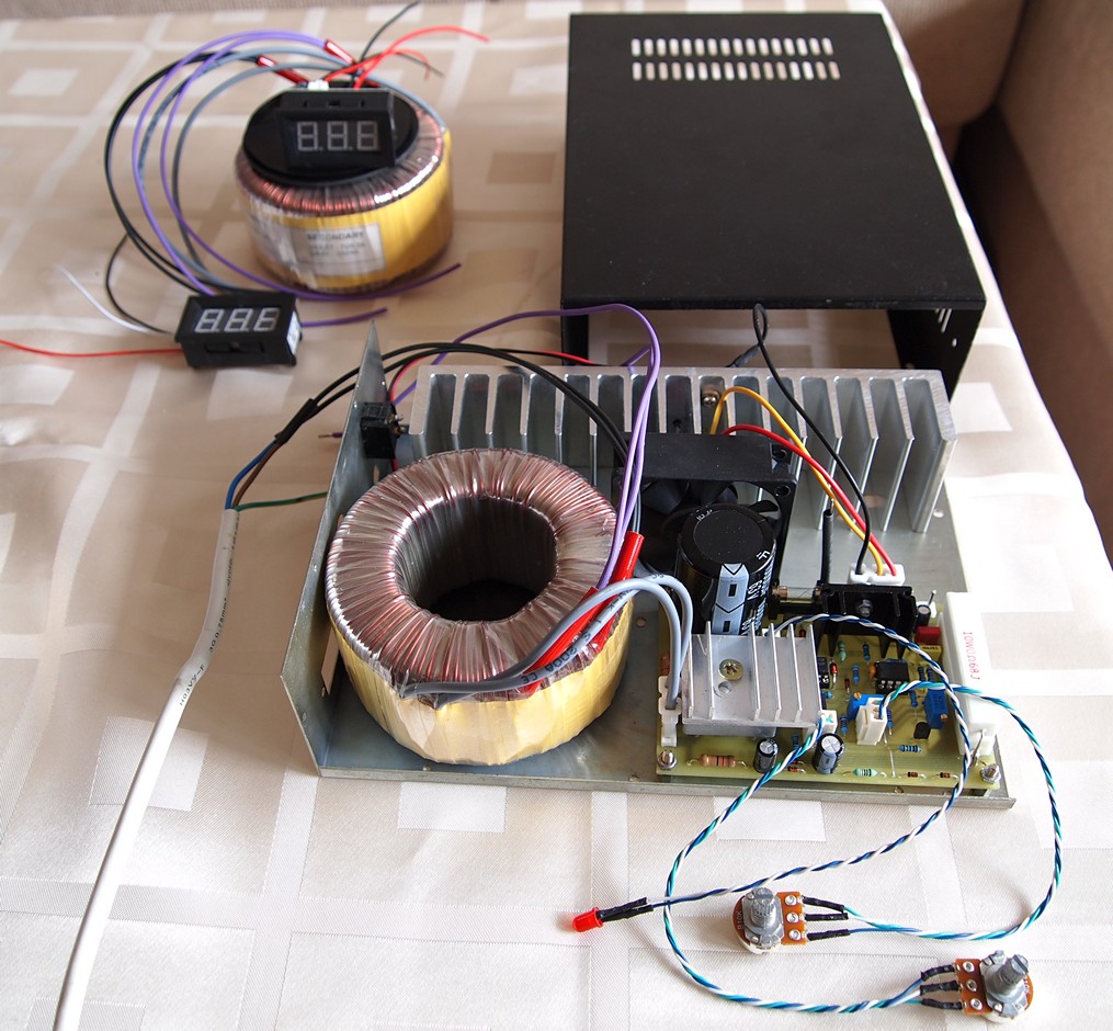
The additional plans were to make 2 pieces in two separate chassis and need dual voltage supply modules
also voltage higher than 30V .Will use both of them.
There are digital meters in the front of the chassis.

Finally, two transformers are ready to go.
They are able to deliver 30V/4A power sources.


As you can see, had replaced 0.47 ohm/10W resistor with two 0.68ohm/10W resistors in parallel,
because the former one had generated too much consumption in heat.
The front panel is also ready.
What else to do is to make a tiny board for fan controller.

Here is the link for downloading archive with project files in PDF format: LabPS.rar

The first one of the two PS is ready!
Here is tiny board for the fan controller:


Teh alone came the power supply :


Here is the schematic of the fan controller:


The schematic may be supplied with AC or DC voltage but not both simultaneously. If the supply voltage is DC, then B1, C2 and J3 may be omitted. With different R7 value it tunes the speed of the fan. Adjusting switch-on temperature is made with TR2.

And here is the link for downloading: FanControl.rar
The PCB is different from the one shown on picture above, because I had made some improvements and component re-locations.

The second unit is almost ready. Here is the internal snap :


The fan is secured on the bottom with double side adhesive tape.

It deliveried good job according to the schematic bellow. The bridge rectifier is replaced with two diodes. 
The negative voltage come from one of the windings. 
It is rectified by D3 and ripple stablized with C3. D1 and D2 must used of higher current rating - 
at least 5A (diodes in the schematic bellow are just for illustration).  
C3 must be 50V or 63V rating. R1 and R2 must be 2W power resistors. 
There can be added a capacitor (100uF) between -V and GND for extra stablized the negative voltage. 
If the negative voltage is bellow 1.3V, then the value of R1 and R2 can be decreased a little. 
Bear in mind that I haven't tried this schematic, just simulated it, so be careful.


2012年11月11日 星期日

@ 來點雜質吧 !

人生不要苛求自己純淨無瑕,試著容納些許雜質 !

如果某些雜質是組成美好的元素,我會有什麼想法???

許久,固態科學家發現將"鍺"提煉可以製成極優異的電晶體之後,
就開始有人嘗試將"鍺"中所有雜質去掉,讓純度達到100%,
卻沒有任何人成功..

SONY 的江崎玲於奈博士與助手黑田百合子逆向奇想 (給"鍺"添加一些雜質)
當江崎博士對眾多同領域高手公佈這想法時,反對與嘲諷接踵而至,
更有者竟公然弔言 (如果透過加入雜質來對"鍺"提煉會成功,除非地球倒轉!!!)
然而,江崎玲於奈-(Leo.Esaki) 博士以此法成功提煉出極為穩定,快速優異的
電晶體-量子隧道效應 (Quantum tunnelling effect),也因此獲頒1973年
諾貝爾物理學獎!

人云 (水至清則無魚,人至察則無徒),
正所謂 (在雜質中,潛匿著深刻的美!!!)


2012年11月3日 星期六

@ 網路世界中的小丑


蝙蝠俠這系列的電影,有一個很矛盾的現象,就是蝙蝠俠永遠都不會是主角(可能因為都戴著面罩,
大家都不會記得蝙蝠俠是誰演的),之所以有那麼多人演過蝙蝠俠,但是沒一個令人印象深刻的。

而『黑暗騎士』也仍然不會打破這個規則,但是它卻出現了一個會令人沒辦法忘掉的惡人代表-小丑
(希斯萊傑-飾演),或許是希斯萊傑揣摩的無懈可擊,這讓『黑暗騎士』一片,幾乎成為專門為小丑
這個角色所打造,極其具有深度的片,也可以說讓黑暗騎士成為希斯萊傑最後完美且成功的代表作。

如果談到希斯萊傑的演技,還真的是無懈可擊,包括他因嘴割裂過會不時吸舔口水的小動作,到小丑
講話有點鴨子的腔調,甚至到小丑走路有點跛有點跳動的模樣,都是揣摩到入木十分之至!更不用說
他演小丑那極其黑暗及扭曲的心裡層面。

在特效化妝的臉龐背後,小丑代表著憤世嫉俗、善於挖掘人類黑暗面等超越世俗想像的個性,卻也因
如此而格外地迷人,這些元素都難以在其他漫畫角色中得以尋獲。希斯萊傑為小丑改變的不光是聲線
發音與表情猙獰,那些基本配備只顯得匠氣,他難得的是把洞悉人性的自信寫在臉上,即使被蝙蝠俠
打到奄奄一息也不改其嘻皮笑臉。

黑暗騎士整個故事可以說完全是環繞小丑而生,小丑代表了人性最黑暗而醜陋的那一面,卻也代表了
最高水準的道德跟無私,很矛盾吧,這個角色如此出類拔萃之處!利用人性的弱點來摧毁人類以達到
某種救贖的意義,這也就是我所說的小丑代表了極高的道德跟無私。

希斯萊傑為了全力投入揣摩小丑扭變的個性卻泥深無法自拔.後來過世而肇因於萊傑同時服用鎮痛藥 
(羥考酮)、止痛劑、抗焦慮藥、鎮靜劑、安眠藥六種藥物來嘗試慰撫自我.

如果我們能用點心,從另一個觀點來發展.跳脫自我矛盾黑暗,反覆拘泥及扭曲矛盾的內心.也許在這個
新網路世界的上層心靈溝通網站,你將是另一位小丑,但不是要你去摧毁人類吧!