The 2014 latest had almost perfect - two channels, 1.2 - 30V/3A -
but there was no current limit. That's why I had search for suitable schematic to build.
What I found is this schematic: http://www.electronics-lab.com/projects/power/001/index.html.
It provided adjustable output voltage from 0 to 30V and adjustable max output current from few
mili-amperes to 3 amperes.
As it turned out there are serious flaws in it, but in the forum where it was thoroughly discussed
and one of the member had proposed an improved schematic, in which all flaws were been addressed.
I used his schematic to build the new power supply.


In the final version
there will be a much bigger heatsink and maybe also a fan.
After built it and did some tests I made two changes:
first, added 24V zener diode and resistor to stabilize supply voltage on IC1.
This is especially important because when there is higher load and supply voltage drops
by some volts the reference voltage on pin 6 would be changed significantly.
Second, had removed 10k trimmer resistor RV1.No need to use it anymore.
Here came the final schematic version:

Some snaps of the PCB and assembled board:


The additional plans were to make 2 pieces in two separate chassis and need dual voltage supply modules
also voltage higher than 30V .Will use both of them.
There are digital meters in the front of the chassis.
Finally, two transformers are ready to go.
They are able to deliver 30V/4A power sources.
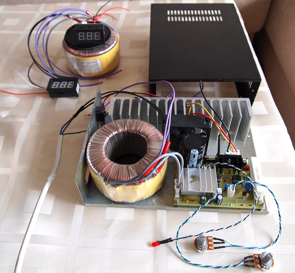
As you can see, had replaced 0.47 ohm/10W resistor with two 0.68ohm/10W resistors in parallel,
because the former one had generated too much consumption in heat.
The front panel is also ready.
What else to do is to make a tiny board for fan controller.
Here is the link for downloading archive with project files in PDF format: LabPS.rar
The first one of the two PS is ready!
Here is tiny board for the fan controller:


Teh alone came the power supply :

Here is the schematic of the fan controller:

The schematic may be supplied with AC or DC voltage but not both simultaneously. If the supply voltage is DC, then B1, C2 and J3 may be omitted. With different R7 value it tunes the speed of the fan. Adjusting switch-on temperature is made with TR2.
And here is the link for downloading: FanControl.rar
The PCB is different from the one shown on picture above, because I had made some improvements and component re-locations.
The second unit is almost ready. Here is the internal snap :

The fan is secured on the bottom with double side adhesive tape.
It deliveried good job according to the schematic bellow. The bridge rectifier is replaced with two diodes.
The negative voltage come from one of the windings.
It is rectified by D3 and ripple stablized with C3. D1 and D2 must used of higher current rating -
at least 5A (diodes in the schematic bellow are just for illustration).
C3 must be 50V or 63V rating. R1 and R2 must be 2W power resistors.
There can be added a capacitor (100uF) between -V and GND for extra stablized the negative voltage.
If the negative voltage is bellow 1.3V, then the value of R1 and R2 can be decreased a little.
Bear in mind that I haven't tried this schematic, just simulated it, so be careful.

