The circuit is an astable multivibrator with a 50% pulse duty cycle.
The difference from the standard design of a 555 timer is the resistance between
pins 6 and 7 of the IC composed of VR1, VR2, R2, D1 and D2.
The diodes D1 and D2 set a definite charging time for C1 which produces a 50% duty cycle
in a normal case.
Dedicated duty cycle (n) is dependent on VR1 and VR2 in the following description:
n [ % ] = 1 + ( VR2 / VR1 )
If VR2 = 0 (n = 100%) then the frequency can be approximately calculated with the following formula:
Frequency = 0.69 / ( ( 2 * VR1 + VR2 + 4.7kΩ ) * C1 )
PWM Generator Circuit Diagram

Thus used VR1 of 20K, VR2 of 100K and 10nF for C1.
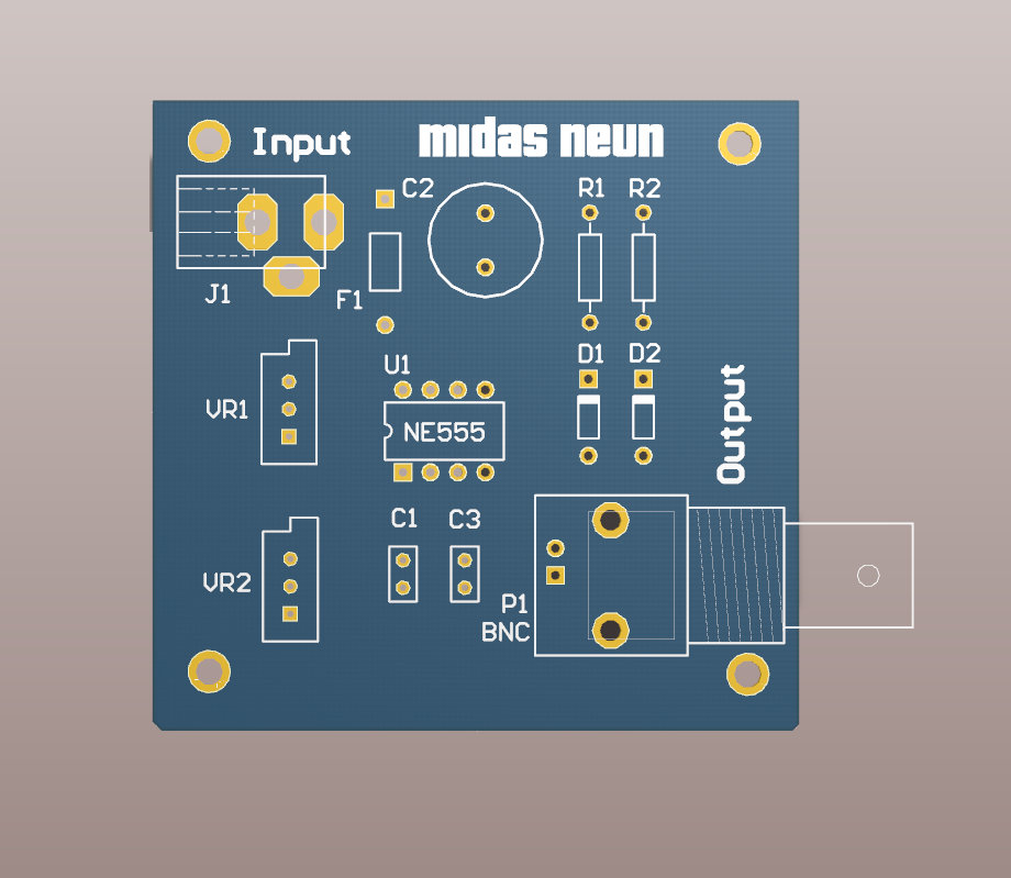
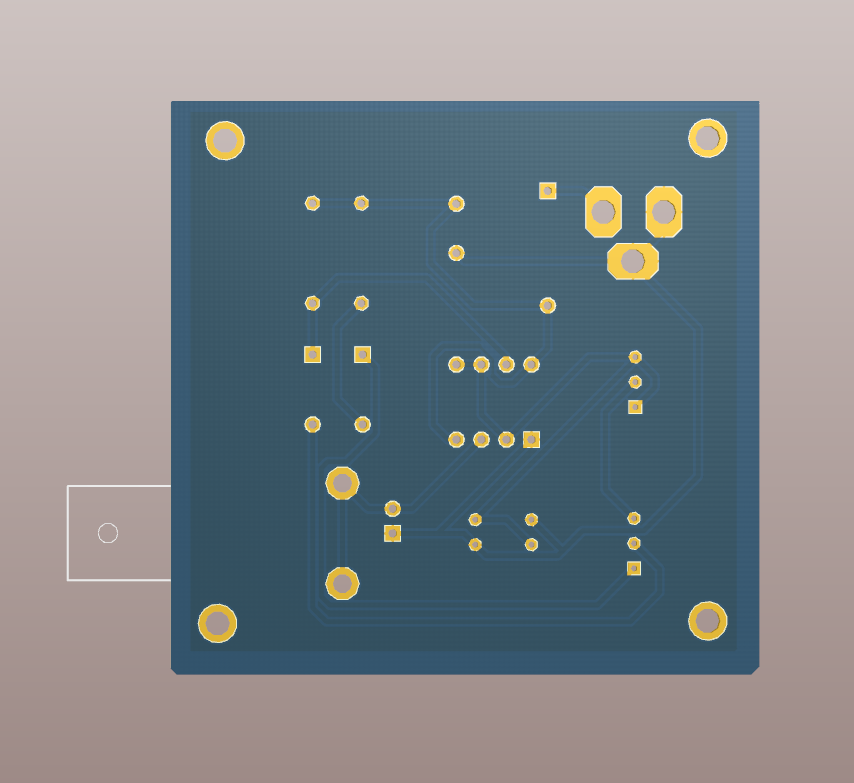
Printed circuit layout of the pulse generator

Next Step

Waveform Captures in my Friend's Lab


沒有留言:
張貼留言